4.22.2011
Final Arduino Project #2 Post
The exhibition went well last night. I was glad to see interest in my work and thought the other Arduino projects were great as well. I definitely plan to work on other projects in the future, so check back here periodically for details! Thanks for reading.
4.19.2011
Arduino Project #2: Update (6)
Yesterday was an extremely long and ocassionally frustrating day. Things worked out in the end, but I was reminded of a very simple and basic rule/lesson about development and just work in general - take periodic breaks! I ended up getting so wrapped up in transitioning everything from the prototype to the switchboard that I made a few mistakes along the way. For one thing, I put all the analog sensor lines in backwards because the prototype setup was opposite of how I had to put it all in the switchboard box. To make matters worse, I made the simple mistake of using an incorrect power pin on the Arduino. The result - nothing functioned in the switchboard box they way it had done in the prototype!
After finally figuring out my mistakes, I rewired everything as it should have been... and voila, success! I had to make a few tweaks/considerations because of Processing, but ultimately I'm happy with the end result. I'll need to attach one of the switchboard housing panels tonight (probably one of the sides rather than the back, just in case people want to look inside to see how it's wired), but other than that - I'm done!
After finally figuring out my mistakes, I rewired everything as it should have been... and voila, success! I had to make a few tweaks/considerations because of Processing, but ultimately I'm happy with the end result. I'll need to attach one of the switchboard housing panels tonight (probably one of the sides rather than the back, just in case people want to look inside to see how it's wired), but other than that - I'm done!
 |
| Everything in its new home! This was taken after I figured out the wiring/pin issues and put all the components back in place... not fun, and I should have taken more breaks during the day! |
 |
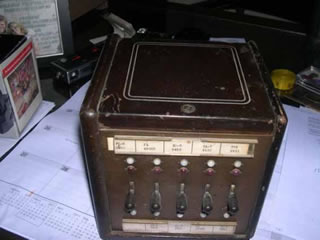
| Final product - front view. |
 |
| The switchboard in action. You can see the images being displayed on the laptop above and behind the unit. |
 |
| Screen shot of the laptop display portion of the project. |
4.16.2011
Arduino Project #2: Update (5)
The prototype was essentially completed and tested by the end of the day as planned. The only task I didn't get to was finalizing all of the images and audio clips I plan to use. I ended up just using some test media files instead. The next big hurdle will come tomorrow when I place everything inside the switchboard box... but for now, I'm done for the day!
 |
| Final prototype test (all five lines) before moving everything into the desktop switchboard unit. |
 |
| My breadboard diagram with all line/jack and LED connection points. |
 |
| The switchboard unit - ready for its new occupant! |
Arduino Project #2: Update (4)
I had a great prototype session this morning! I rewired the LEDs as they need to be and then, most importantly, got the interface between Arduino and Processing working. Processing is successfully reading when each individual line is engaged and acting accordingly - which at this point is just turning the corresponding LED on. Later this afternoon I'll finish work on the prototype and get Processing to display/play the media elements I plan to use for when each line is engaged. If all goes well, tomorrow I'll move everything into the actual desktop switchboard unit itself.
 |
| Prototype test using three lines. |
4.13.2011
Arduino Project #2: Update (3)
Another successful (well, mostly successful) test last night! I created a very basic mock-up of the switchboard interface, wired everything up, and then verified that all lines and jacks (for now I just tested with 3 out of the eventual 5) are generating readable signals. Other than an initial problem with some touching wires from two separate jacks, I was able to get successful readings from all three input jacks regardless of which line was plugged in (which is what I wanted).
I did have an issue with the LEDs I plan on using, but that was only because I tried wiring them up a different way (using the existing wires from the input jacks) in order to minimize the number of wires/connections inside the switchboard. I'll go back to the way I'm supposed to wire them!
The next test before the final build this weekend will be to add the other two input jacks, rewire the LEDs, and complete the interface/coding between Arduino and Processing.
 |
| It's certainly not pretty - but it works! Front view of the prototype (with just initial three lines connected). Note: the right LED is not illuminated - it just appears that way due to the camera flash. I need to rewire the LEDs as they should be, not by trying to use the input jacks. |
 |
| Back view of prototype with breadboard and Arduino showing. |
 |
| Serial monitor from Arduino is successfully reading signals from all three lines. The value of 1022/1023 indicates that a line is plugged in, while a value of "0" indicates that the line is not plugged in. |
4.07.2011
Arduino Project #2: Update (2)
The antique switchboard arrived yesterday and I took some time last night to open it up and see what I have to work with. I'll need to remove quite a bit of the innards, but overall the exterior parts will work great - the audio jacks even fit almost perfectly into the existing holes. More to come...
 |
| The innards of the original desktop switchboard unit. |
 |
| ...at least the cables will fit easily through the front holes! |
4.04.2011
Arduino Project #2: Update (1)
The other day, I completed my initial proof-of-concept test for the Arduino interactive switchboard project. Using a 1/4" instrument cable, which will serve as the switchboard cable(s), I simply wanted to verify that I could hack the inside of the instrument cable and wire up one positive end to the Arduino/breadboard and the other positive end (tip) to the jack plug - thus completing a circuit and getting a signal on the analog (0) input of the Arduino. The test was a success. With the cable disconnected from the jack, the reading was 0. Once the cable was plugged in, I got a reading that varied from 600 to 650 - which is fine as all I wanted to do was to get something other than 0.

The next step is to further prototype the switchboard (using a peg board panel) by connecting all four cables and input jacks. After verifying that I'm getting signals on all cables, regardless of the number and combination of cables plugged in, I'll need to map the various cable configurations over to the Processing display portion.
The next step is to further prototype the switchboard (using a peg board panel) by connecting all four cables and input jacks. After verifying that I'm getting signals on all cables, regardless of the number and combination of cables plugged in, I'll need to map the various cable configurations over to the Processing display portion.
4.03.2011
Arduino Interactive Art Piece #2
For the final project in my physical computing grad class, I will be creating an interactive, Arduino-controlled art piece.
"Switchboard Operator"
This interactive art piece is a statement on how our methods of communication have changed, and in some cases remained the same, over the years. Using antique components alongside modern-day equipment, the piece is a reflection of how we have now become our own individual switchboard operators - making multiple communication points with multiple devices. Whereas in the past, we looked to others to make connections for us, we now have the ability to make our own connections - both global, instantaneous, and diverse.
The plan is to use an antique switchboard (the input/interface portion) with an Arduino w/ a wave shield that interfaces with a laptop (the output/display portion). I will be using Processing along with Arduino in order to generate the visuals. Below are the images of the antique switchboard (desktop model) as well an old switchboard toy. Both were purchased on ebay and should hopefully arrive within the week. Most likely I will be primarily using the desktop switchboard and add some pieces from the switchboard toy (e.g., the phone). If I run into any delivery delays, I have a backup plan to construct an antique-looking switchboard myself.
Subscribe to:
Posts (Atom)